This project turns the Raspberry PI into a logic sniffer that is compatible with sigrok.
The logic sniffer runs on "bare metal": it doesn't require Linux to run.
This is what you need to use the Raspberry PI as a logic sniffer:
- A SD card containing the binary here
- A serial cable like the one here
- A computer running sigrok
Features:
- max samplerate 3 MHz
- 16 probes
The sniffer currently relies on Sigrok for control and signal analysis. Note that there are
cheap special purpose logic sniffers on the market with much better specs than listed here.
So don't get a PI just to run this software. But if you own several PI's for other reasons
(some examples here, and lots of inspiration to
be found here) and happen to need a logic
analyzer then this project can be of help.
The strong points of the PI are yet to be exploited in this project. The HDMI and USB ports on the
device make it relatively easy to turn the sniffer into a standalone logic analyzer, making the
connection with sigrok optional. That is something a (cheap) special purpose logic sniffer cannot do.
Running the sniffer
Compile the sniffer using the instructions and source here,
or setup an SD card using the binary as described above. Just download the tarball, unpack and read INSTALL_BINARIES.
See the demonstration below for information how to run the sniffer using sigrok.
Warning: the GPIO pins on the Raspberry PI use 3.3V. Do not connect 5V logic, or anything else that isn't limited to 3.3V.
And if you do connect something that uses 3.3V (like another PI) then before anything, do connect ground first.
Visit https://github.com/tuxyme/metal-pi for more information, source code and
a MD5 checksum for the tarball on this site.
Demonstration: sniffing Nokia 3310 LCD signals
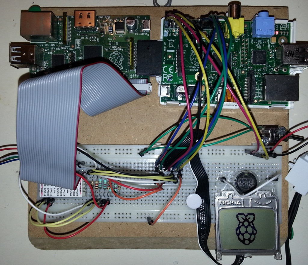
This photo shows the test setup with two Raspberry PI boards. The revision 2 board on the right runs
Raspbian and drives the LCD display with code based on this
code by Adafruit
(port to Raspberry / bare metal work in progress). The revision 1 board on the left is booted as 'Raspalyzer' and sniffs the
LCD clock, data, d/c, cs en reset signals (pin 2,3,4,5 and 8 on the 3310 LCD) while
the Raspberry PI logo is drawn on the LCD.
The board on the left is connected to a PC using this USB to serial connector.
The serial connection is available on the PC (running Linux) as /dev/ttyUSB0. The sniffer is started using sigrok-cli, and the
resulting sigrok session data is opened with PulseView.
Command given on PC:
sigrok-cli --driver=ols:conn=/dev/ttyUSB0 --config samplerate=3000000 --samples 100000 --probes 1=CLK,2=DIN,3=DC,4=nCS,5=nRST --triggers nCS=1 -o test.sr
- --driver: The sniffer identifies itself as a Open Bench Logic Sniffer (OLS) on port /dev/ttyUSB0
- --config samplerate: using the maximum of 3M samples/s
- --samples: 100000 samples (taking ~33ms at 3 MHz)
- --probes: probe 1-5 are used, the labels are optional
- --triggers: the sampling starts after probe 4 (nCS, inverted chip select) turns high
- -o test.sr: the session is saved to a file that can be read by PulseView
The probes relate to the GPIO ports of the PI as:
| SUMP probe |
0 | 1 | 2 | 3 | 4 | 5 | 6 | 7 | 8 | 9 |
10 | 11 | 12 | 13 | 14 | 15 |
| Rev 1 GPIO |
7 | 8 | 11 | 9 | 25 | 10 | 24 | 23 | 22 |
21 | 18 | 17 | 17 | 17 | 17 | 17 |
| Rev 2 GPIO |
7 | 8 | 11 | 9 | 25 | 10 | 24 | 23 | 22 |
27 | 18 | 17 | 28 | 29 | 30 | 31 |
This gives 12 probes on the rev1 board, 16 probes on rev 2 (if using the P5 header).
The I2C and GPIO clock pins are reserved for future use.
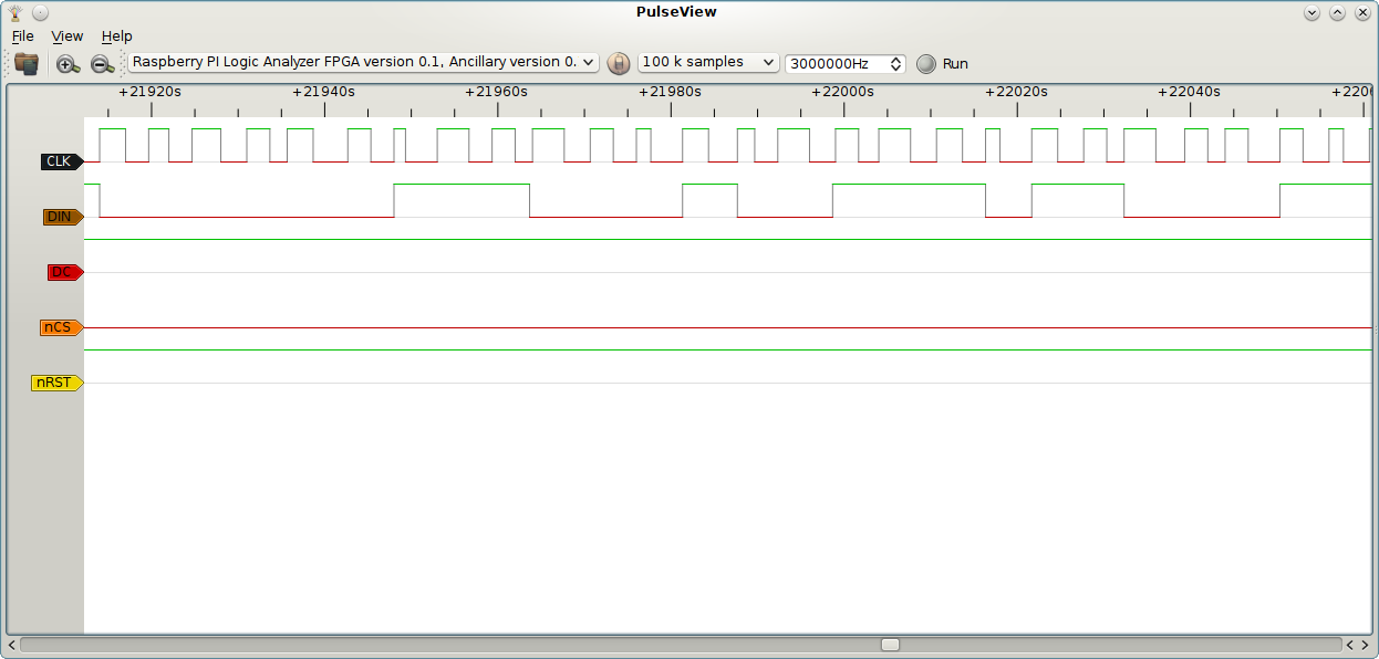
PulseView screenshots
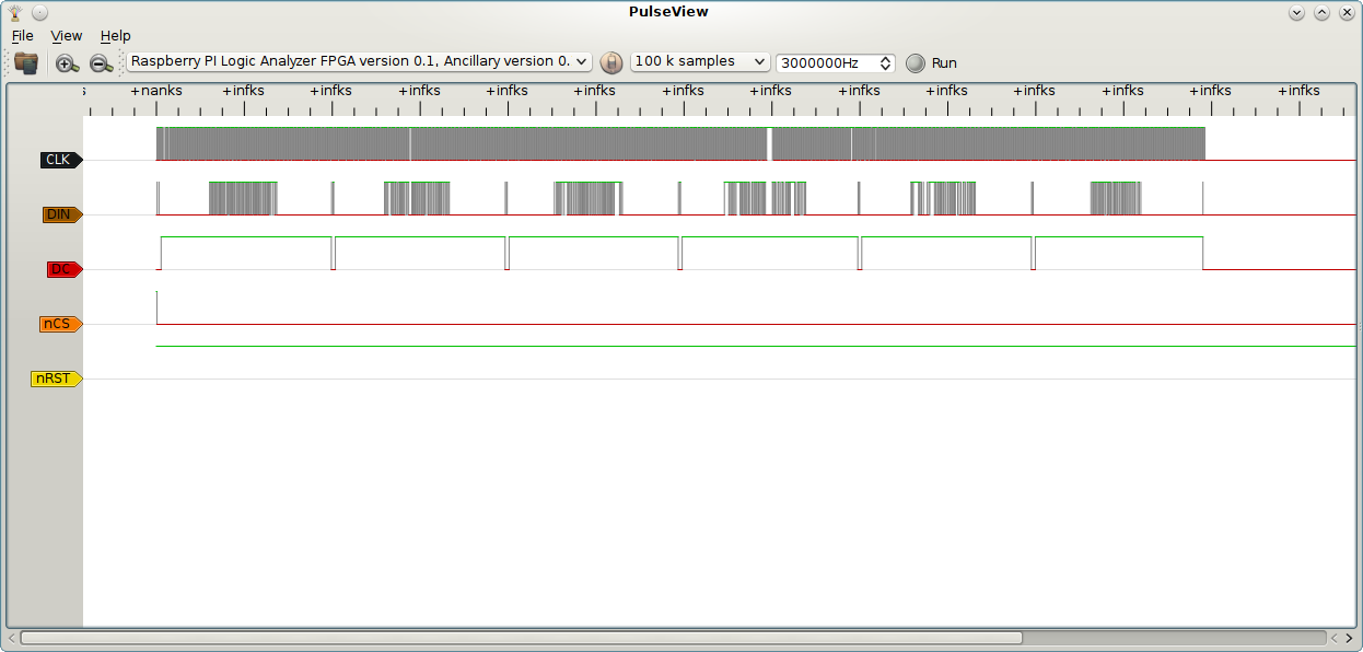
The LCD display is written in 6 lines seen as the 6 broader data bursts on the DIN (data in) line. The shorter
data bursts occur when the DC (data/command) line is low. These bursts are commands that place the cursor in the
correct position. The +nanks and +infks labels should have been timestamps, but PulseView has a problem reading
the correct time from the sigrok session data. This might have something to do with version mismatch between
PulseView and Sigrok on my PC.
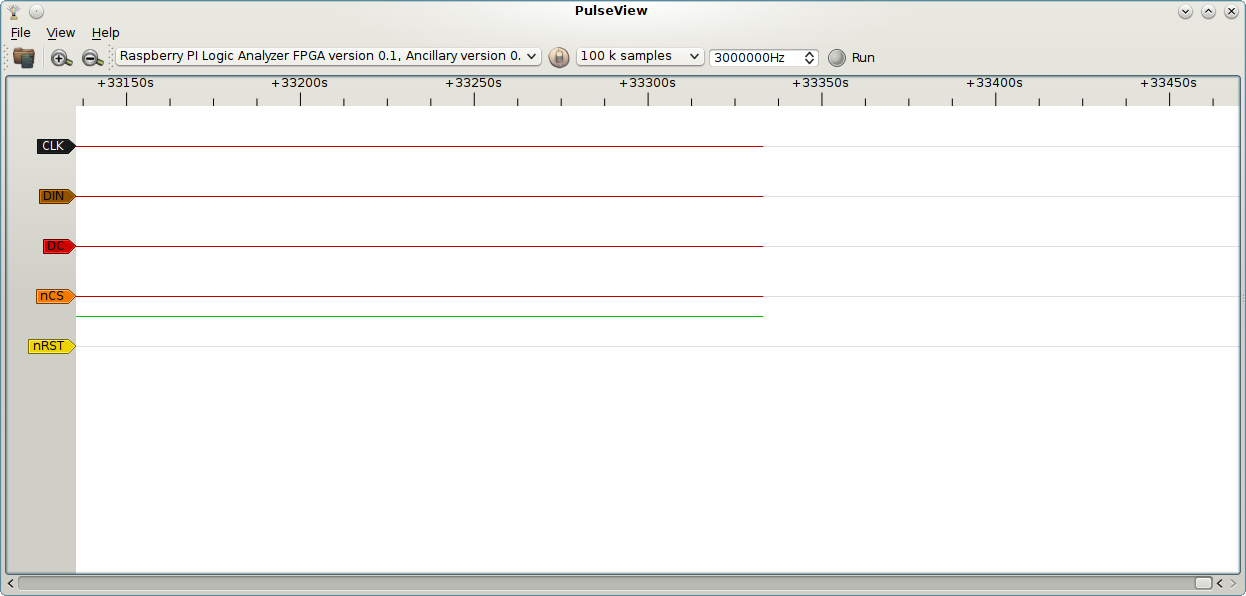
Zoomed in at the end of the sample window showing a sample duration of 33300s. With 100000 samples at 3MHz this
should read 33300us. Again, might be the version mismatch. Working with libsigrok from git, installed PulseView
from a deb.
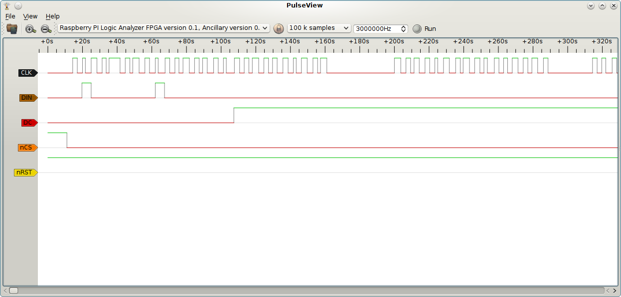
Zoomed in at the beginning of the sample window showing the nCS (inverted chip select) initially at high level,
satisfying the trigger nCS=1. I added debug code to the driver that toggles chip select. This makes it very
easy to trigger the sniffer at the right time. Also visible are two bytes sent during DC=low: 0x40 and 0x80,
command cursorY=0, command cursorX=0 respectively.
Zoomed in on a data section. Clock jitter is visible. No suprise given the bit-banged LCD data. When a stable
clock approaches a speed comparable to the sniffer samplerate the same picture can be seen, but then caused by
the limited resolution of the sampling. At clock speeds higher than the samplerate the sniffer will miss clock
pulses. Using a sniffer can easily become as complex as building one.